I am attempting to measure smoke in a small chamber through optical obfuscation using a TCRT5000 phototransistor. I'm taking measurements with an Arduino Nano.
My current configuration is:
- \$R_l\$ is a 10k resistor
- \$V_{cc}\$ is 5V
- The IR diode resistor is 100ohm
The problem I am facing is that the sensitivity with this configuration is too low.
Here is a graph of the recording:

As you can see, the effective range is between 232 and 214 (this is the 10-bit ADC values bitshifted down to 8-bit).
What I need to do is change \$R_l\$ to move the range of the phototransistor to be more sensitive within this range since I do no expect values smaller than about 200.
What are the steps to calculate the \$R_l\$ value on my desired range?
Edit
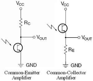
Here is the schematic:
I have the circuit configured as the Common-Emitter Amplifier type. In this case, my above reference to \$R_l\$ should be changed to \$R_c\$
Am I able to just adjust \$R_c\$ to change the range of the circuit?
Answer
I'm just going to take some of your numbers and guess from there. You are running your IR emitter LED at about \$35\;\textrm{mA}\$ and you are getting returned collector currents from around \$47\;\mu\textrm{A}\$ to \$82\;\mu\textrm{A}\$, given your shown ADC values. (Assuming a \$5\;\textrm{V}\$ rail and your \$10\;\textrm{k}\Omega\$ collector resistor.) So that's about the range you want to see and you'd probably like it spread out over your \$5\;\textrm{V}\$ ADC input range, too.
I prefer the idea of allowing you to set the forward current in the IR emitter LED. You may want to do this from your controller. But so far, you haven't asked for that. So, to keep it simple, I'll just make this an adjustable bit of hardware. Allowing you to change the IR emitter LED current will allow you to make one kind of adjustment for whatever reflector you are using, and its distance, coupled with the density of smoke that interferes. However, the absolute max states \$60\;\textrm{mA}\$, so let's not allow more than something less than that.. say \$50\;\textrm{mA}\$ maximum. (Not recommended, either. But there may be times when you don't care.)
Other than that, it's a good idea to keep the \$V_{CE}\$ of your opto-transistor fixed, as well. There is a bit of stuff going on in the curves shown in Figure 7, which makes me want to fix the value of \$V_{CE}\approx 4\;\textrm{V}\$, or so. Do so places you right in the middle of some nice flat areas of the curves there.
Finally, you need to be able to set thresholds, so that the voltage input to your ADC doesn't move from \$0\;\textrm{V}\$ until some minimum current is reached. Then it rises, until some limit is again reached, where it rails at the top. This will give you a maximum resolution into the area of interest.
So here's an idea to try:

simulate this circuit – Schematic created using CircuitLab
In the above design, \$R_3\$ adjusts your IR emitter LED current, up to around \$50\;\textrm{mA}\$. It uses a standard \$1\;\textrm{k}\Omega\$ potentiometer, which are pretty easy to get. The value of \$R_1\$ establishes this range. I figured a maximum of about \$2.5\;\textrm{V}\$ at the emitter of \$Q_1\$, so the value is then \$R_1=\frac{2.5\;\textrm{V}}{50\;\textrm{mA}}=50\;\Omega\$ and I used the next standard size down from that.
The value of \$R_5\$ sets the gain. In this case, I decided to give you a range of from \$40\;\mu\textrm{A}\$ to \$90\;\mu\textrm{A}\$, which means a \$\Delta\;I=50\;\mu\textrm{A}\$. With an output that ranges from \$0\;\textrm{V}\$ to \$5\;\textrm{V}\$, then \$R_5=\frac{5\;\textrm{V}-0\;\textrm{V}}{90\;\mu\textrm{A}-40\;\mu\textrm{A}}=100\;\textrm{k}\Omega\$. So that is where that value came from.
The value of \$R_4\$ sets the minimum current that this range starts at, which in this design is \$I_{min}=40\;\mu\textrm{A}\$. I set a voltage divider up to the (+) input of the opamp to make sure that the current mirror collector is above a volt or so. I picked \$V_{ref}=2.5\;\textrm{V}\$ as the middle of your voltage range. It could be different. But that's where I placed it. (I did that to provide enough \$V_{CE}\$ for the current mirror and to also provide for the possibility that you might want to use discrete BJTs for the mirror and would therefore need some added emitter resistors [discussed at the end, below.]) So when the opamp output is still at \$0\;\textrm{V}\$, there will be come current flowing through \$R_5\$. That also has to be accounted for. So the value of \$R_4\$ will be set as:
$$ R_4=\frac{5\;\textrm{V}-V_{ref}}{\frac{V_{ref}}{R_5}+I_{set}}\approx 39\;\textrm{k}\Omega$$
So this allows you to make adjustments to your IR emitter LED current, within a reasonable range, and allows you to design \$R_4\$ and \$R_5\$ per your needs at the ADC, as well.
I specified a nice current mirror pair designed for the purpose. The BCV61 contains a pair of NPN BJTs on the same die and they will be reasonable here. They are also cheap to get.
However, if you do decide to use discrete BJTs, then please add two resistors to the above design. With your current range of currents, these would be both have a maximum of \$10\;\textrm{k}\Omega\$; one placed between the emitter of \$Q_2\$ and ground, and one placed between the emitter of \$Q_3\$ and ground. But to provide flexibility for higher currents, I'd probably recommend using \$1\;\textrm{k}\Omega\$ values, instead, and then just forget about them. That should be fine for up to ten times the current, which I doubt you will ever need here.


No comments:
Post a Comment