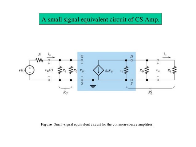
This circuit is equivalent to small-signal common source JFET amplifier:

If you look at the input and output impedance you can see that Zin = R1 || R2 and Zout = rd || Rd || Rl. It can be seen from the small-signal model.
But shouldn't small-signal model look like this?

I just want to understand these models and maybe derivate input and output impedance myself.
Answer
The ideal DC voltage source has 0Ω internal resistance. And that's why AC-signals are shorted by DC voltage source. DC voltage is always constant so for any change in current there is no change in the voltage. So there is 0 Ohm internal resistance. Additional in real life circuit we always uses a bypass capacitor connect parallel to DC Voltage. And this capacitor will short all AC-signal to the ground.
For example if we have a 9V DC voltage source, now if we smoothly change the current that is draw from this DC voltage source, from 40mA to 20mV (we change the resistance from 225Ω to 450Ω). We create AC-current. But the DC voltage do not change (0Ω internal resistance). So the dynamic resistance of DC-voltage source is equal to rd = 0V/20mA = 0Ω And this is why we say that DC-Voltage is a short for an AC-signals.
No comments:
Post a Comment