Just kindly share what kind of input in the violet dot at center to inject so the red fault led would turn on?
When the GFCI no longer function, the red led lights up. I'd like to understand how the circuit detects it. Please focus on the one in blue. The one in red is the electronic reset button. The one in black is the original circuit in the datasheet. It is the same chip as the Fairchild RV4141A popularly used. http://datasheet.elcodis.com/pdf2/81/73/817329/rv4141a.pdf
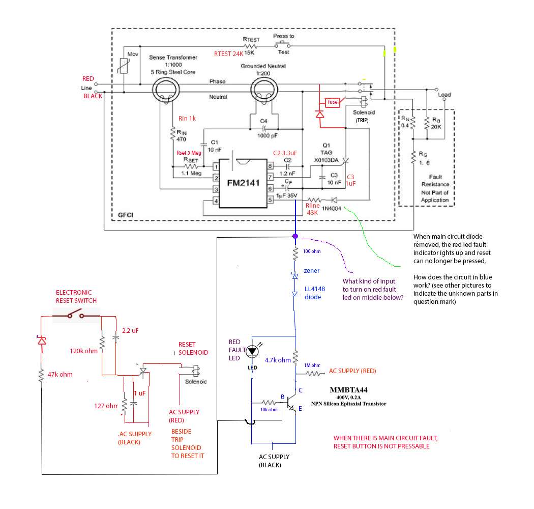
See full circuit diagram at https://imageshack.com/a/img923/6796/7i3hHP.jpg
Here are the two solenoids. One to open contacts, one to close contacts, in the USA, the closing of contacts or Reset is mechanical hence no second solenoid.

When you remove the main diode, the red LED lights up. What kind of circuit in the blue section can do that?
(I have another open question, asking for help identifying unknown diodes and an SCR/transistor(?) shown in that schematic, so I can't mark their types on the schematic yet.)


No comments:
Post a Comment