I am new to the telecom simulations system specially multisim, which I am having a project that I want to simulate.
My project in (Analog Communications) is consisting to have FM Transmitter (Modulator) that accepts a generated signal (Sin, Cos) and get me the modulated output as a Graph.
I've found this FM transmitter circuit (3 km range):
 ![two muppets][1]
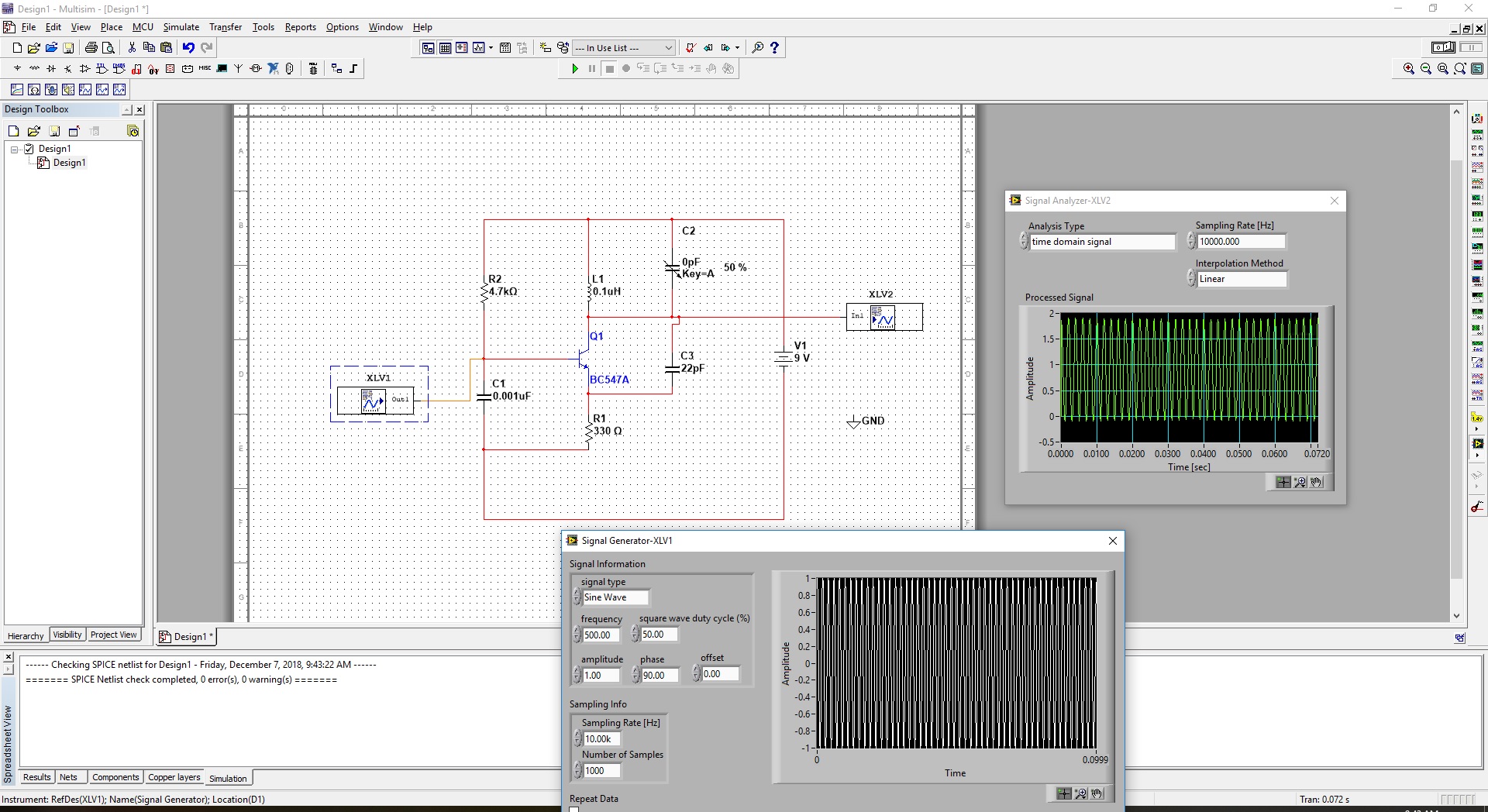
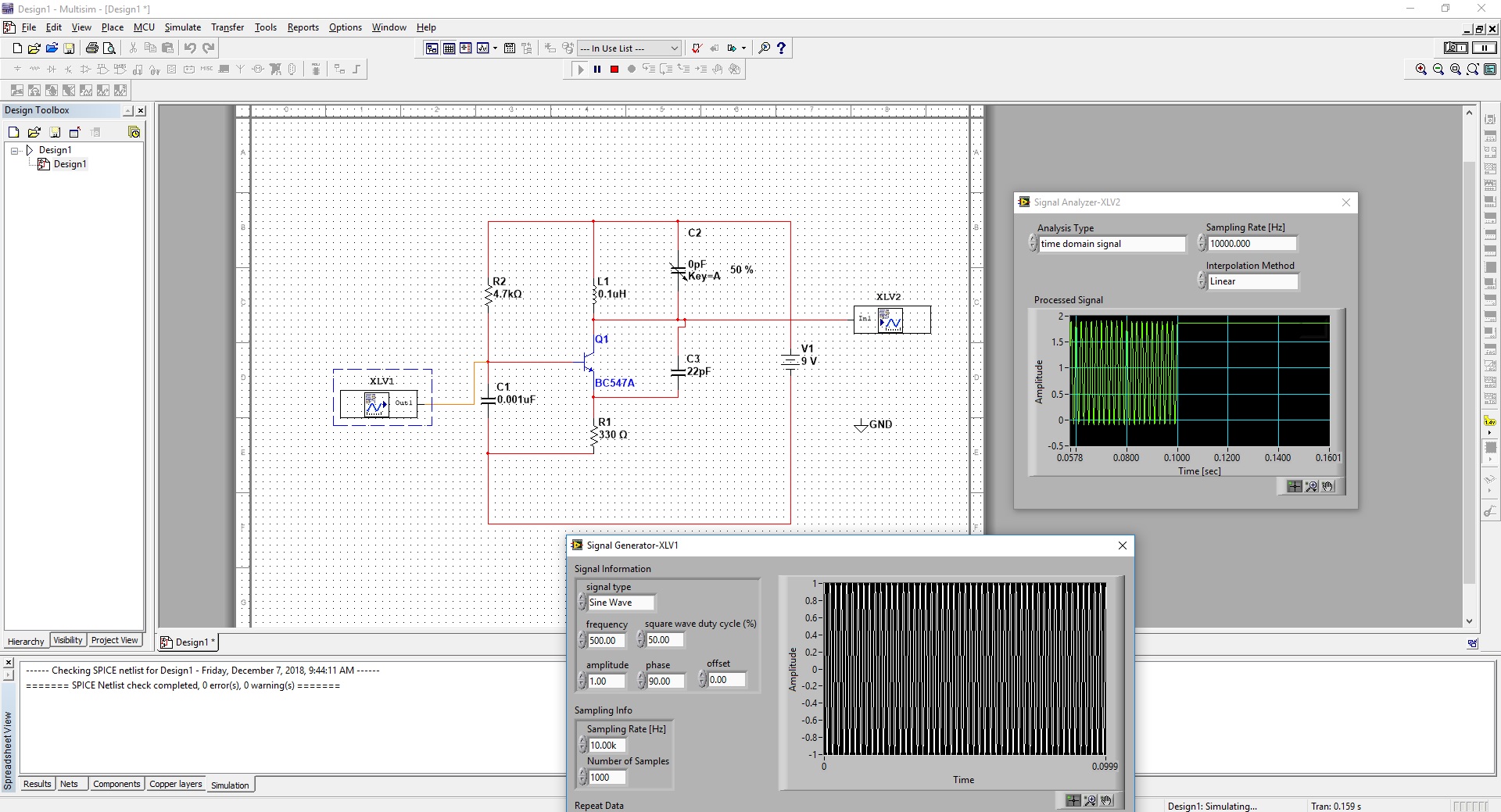
and I am building that circuit on Multisim, and I failed. Because I faced many problems, first of, the variable capacitor symbol is weird here in the multisim, and the regular capacitor doesn't have variable options. Secondly, when I Use signal generator as (Sin, Cos), the output gets weird after 5 second of the simulation.
I want to show the input signal (before modulation) and the output signal (transmitted or modulated).
I guess my output result where not the as expected, as the signal (Sin with phase 90°) is giving weird result of few seconds of simulating.
Below are screenshots of the simulation results within time.
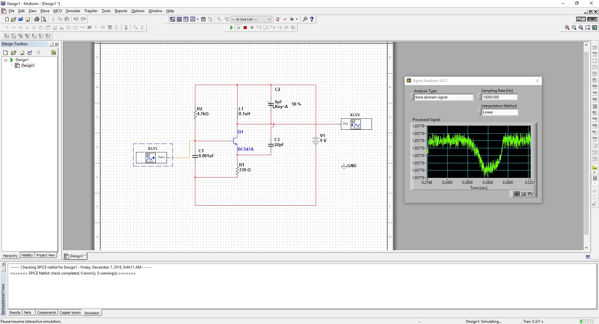
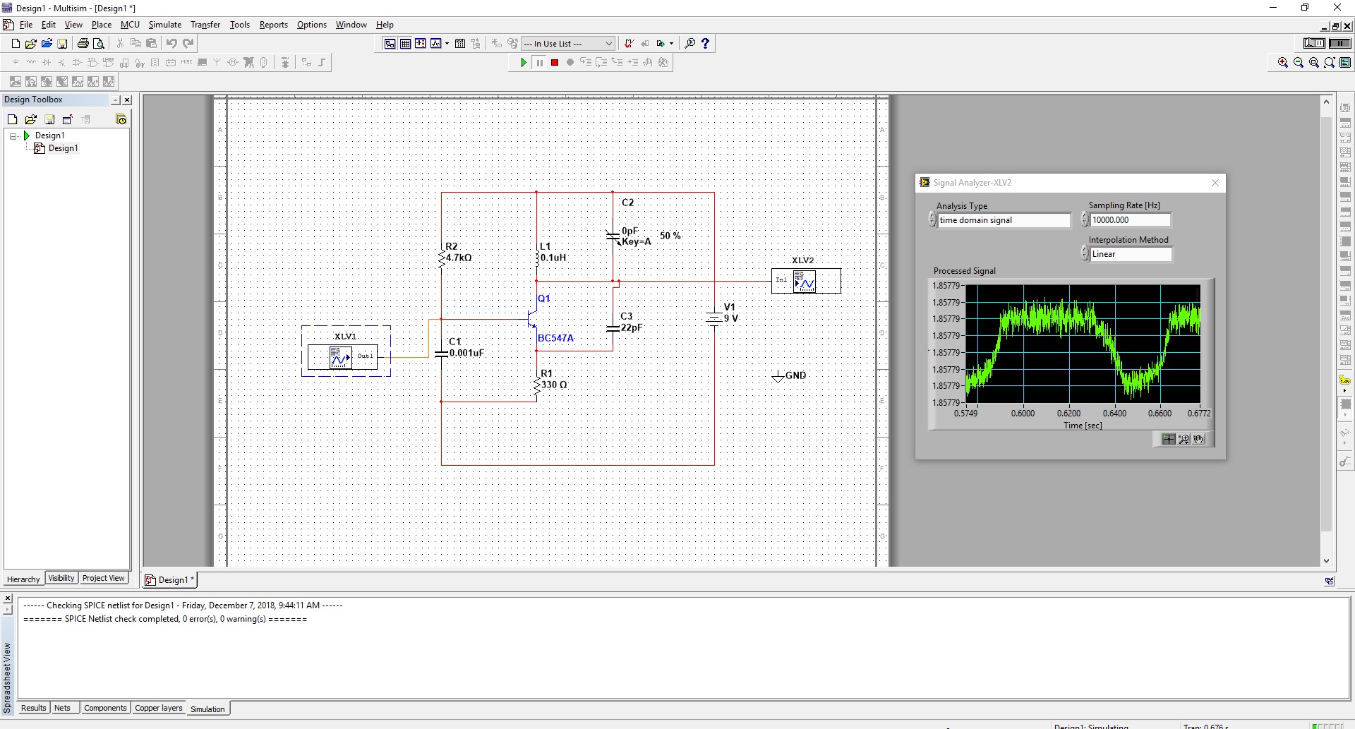
Any ideas how to edit or fix the above circuit to have this output is similar to what it should be?


No comments:
Post a Comment