I am building a somewhat out-of-the-ordinary guitar pedal that involves some synth elements, namely controlled voltage. I'm a little confused by something that I suspect is actually pretty basic.
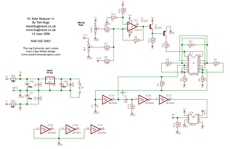
I am pretty comfortable with circuit diagrams for guitar distortion and overdrive effects, but this pedal uses controlled voltage, and I am being thrown off by the "CV1" and "CV2" markings on the linear pots on the upper left. As I have no experience with controlled voltage audio, I don't actually know WHERE or WHAT to connect these leads to. I understand these to be Controlled Voltage 1 and Controlled Voltage 2, but I am uncertain of what these represent in terms of the audio components, and where they lead to/from. As they terminate in X markings, they don't resemble the other voltage markings on the schematic, this is also confusing.
THIS is the circuit diagram I'm working from. 
This is probably a pretty nooby question, but I appreciate any and all help!


No comments:
Post a Comment