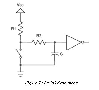
I'm looking to debounce the output of a rotary encoder I'm using as a switch to ground with a pull-up. Looking online I saw the debouncing circuit in Figure 2 and read about it here. However, I also saw the first image below and read about it here. Is one better than the other for my application? According to the datasheet, the GPIO of the imx6sl I'm using has a Schmitt trigger and input hysteresis, so I'm assuming having a capacitor connected to it is okay.
Figure 1


Answer
Assuming the MCU and Schmitt Trigger have infinite input resistance and modeling them as an open, we can close the switch and see what happens.
With the switch closed in the figure 2, the resistor R2 is in series with the capacitor, meaning that there is 0V DC at the input.
In the first diagram, with the switch closed, the resistor R is in parallel with the capacitor meaning that there will be a voltage at the input unless Rpull-up >> R, making the voltage drop across R negligibly small. having different resistor values would mean that the time constant would be different for charging and discharging and our debounce would be inconsistent between rising and falling edges.
Therefore, the first image is not a viable alternative to figure 2 and also does not properly debounce the switch. Figure 2 is preferable.


No comments:
Post a Comment