I am an electronics novice. :)
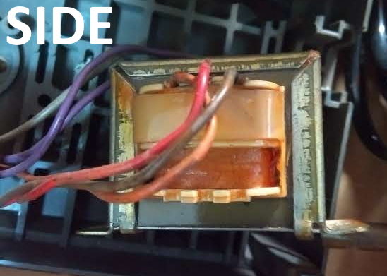
I opened a working Casio vintage desk calculator (likely from the late 1980s/early 1990s). It has a 220 volt step-down transformer with six secondary wires. The two mains wires go into the transformer at the bottom. The 6 wires come out from the sides (three on each side). Following are the related images:
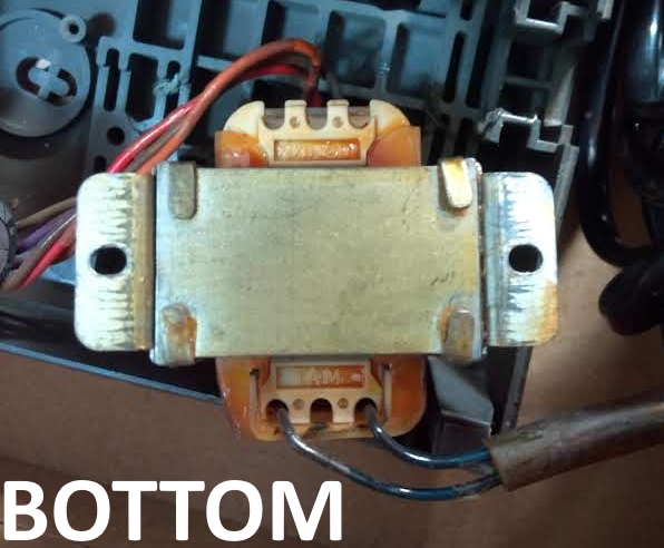
I found out continuity among the secondary wires as follows:
Purple-Grey-Purple: Continuity (side one)
Orange-Red-Brown: Continuity (side two)
However, the wires are wired to six separate contacts on the circuit board.
Are there differences in terms of voltage among each set of wires coming from the same side? If each carries a different voltage, how can I test this with my multimeter? I would appreciate guidance for using my multimeter safely/correctly.
If there are no differences among each set of wires exhibiting continuity, why were they wired separately?
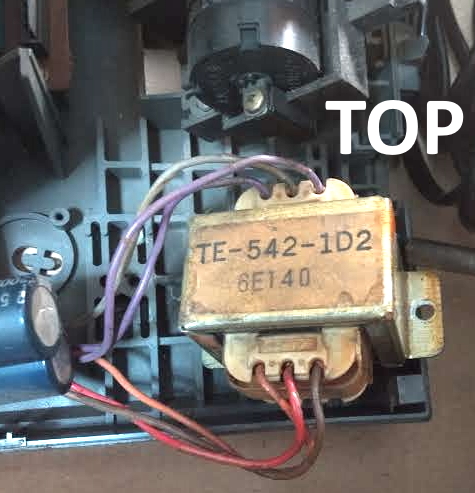
Also, do the markings on the transformer mean anything? There's also another, smaller marking (not visible in the images) that says "E41-2L11/2".
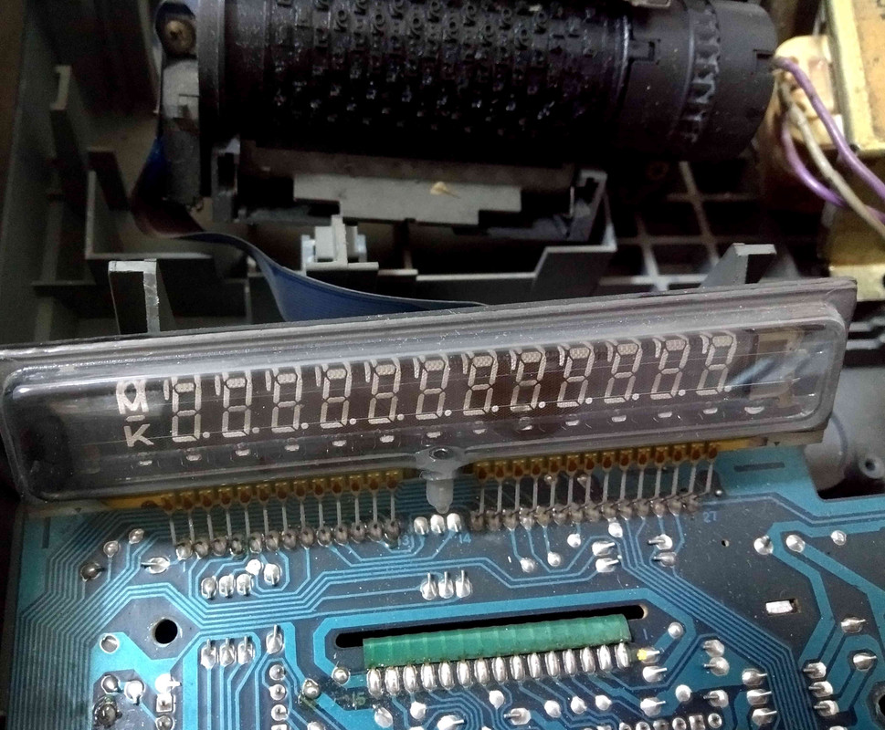
Update: The calculator has an integrated printer, and therefore a motor. (Thank you TimWescott.)
Update: Calculator display:
Answer
Are there differences in terms of voltage among each set of wires coming from the same side? If each carries a different voltage, how can I test this with my multimeter? I would appreciate guidance for using my multimeter safely/correctly.
No continuity between the two sides means two windings that are isolated from each other. The separation between the two windings at the top and the winding at the bottom indicates an additional level of physical and electrical isolation between the primary and secondary.
The purple-grey-purple winding is likely a center-tapped winding. Yon can expect the voltage between grey and each purple to be half of the voltage between purple and purple.
The brown-red-orange winding likely has a tap somewhere other than the center of the winding. The highest voltage will be the sum of the other two, but the two lower voltages might not be equal.
Since the calculator is working, there does not seem to be any reason to check winding resistances. If the condition of the transformer had been unknown, prior to applying voltage, you would check the resistance from each lead to every other lead and the frame of the transformer.
The best way to use the multimeter would be to set it to an AC range that is higher than 220 volts. Apply 220 volts to the primary and measure all of the secondary voltage combinations. They will presumably be considerably less than 220 volts. Once you know the approximate voltages, you can use a lower voltage setting.


No comments:
Post a Comment